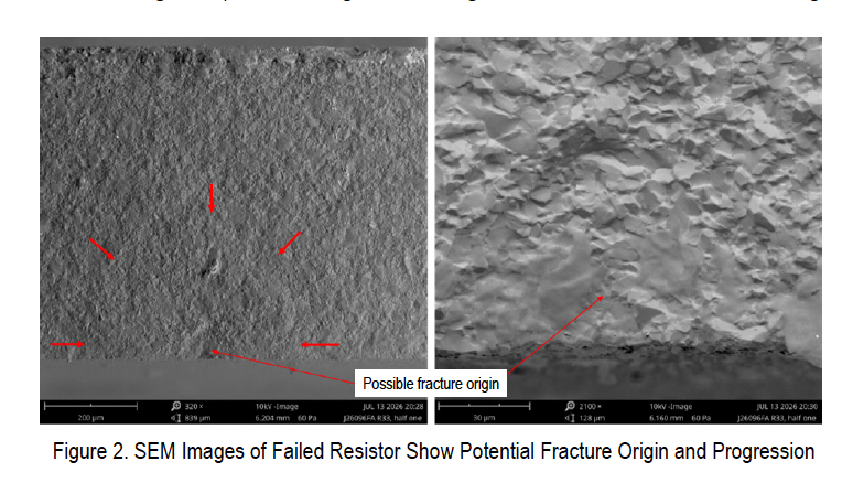
NASA's Engineering and Safety Center documented two instances of thick-film chip resistor cracking on printed circuit board assemblies during environmental testing. Both resistors fractured across their short axis during thermal cycling that followed vibration testing, producing intermittent open circuit failures at elevated temperatures that recovered at room temperature.
The resistors, case size 2512, were positioned near board edges with their long axes parallel to the card edges. Failure analyses by independent teams ruled out defective production lots and fatigue damage. Optical and scanning electron microscopy found no clear initiation sites for crack propagation.
Contributing factors included board flexure, component orientation, excessive solder extending to the top pads of resistor terminations, mounting stresses from hard fastening to rigid frames, and suboptimal fastener torquing patterns. The resistor lot met MIL-PRF-55342 requirements, and additional testing revealed no evidence of elevated defect risk.
NASA's bulletin recommends orienting large ceramic components to avoid parallel alignment with board edges, performing finite element analysis for stress and displacement margins, keeping solder off termination top surfaces, inspecting solder joint fillets according to manufacturer limits, and conducting one to three thermal cycles with hot-dwell functional tests before vibration testing. Joel W. Sills at Langley Research Center authored the technical bulletin.