When two identical thick-film chip resistors failed during environmental acceptance testing on printed circuit board assemblies, NASA's Engineering and Safety Center faced a puzzle: how could components meeting the rigorous requirements of MIL-PRF-55342 suddenly crack during thermal cycling after vibration testing? The answer reveals an uncomfortable truth about aerospace component qualification. The resistors, installed in similar locations near the edge of their respective boards, exhibited transverse fractures running parallel to their terminations—clear evidence of bending stress rather than manufacturing defects or fatigue. Yet the production lot passed all additional tests designed to catch defective components. The real culprit was hiding in plain sight: the printed circuit boards themselves.
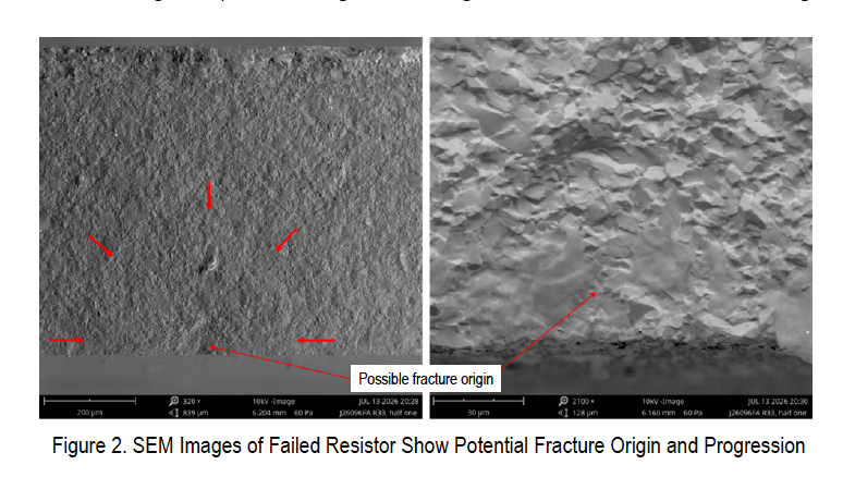
The failure analyses conducted by independent laboratories, including optical and scanning electron microscopy investigations, ruled out the obvious suspects. Fatigue vibration damage showed no evidence in either resistor. No clear crack initiation sites appeared under magnification. The damage signatures simply did not match cyclic fatigue patterns. This elimination process forced researchers to confront a more uncomfortable conclusion: the problem was not the chip resistors meeting MIL-PRF-55342 specifications, but rather how those components interacted with their mounting environment.
The contributing factors identified by the NESC—board flexure, component orientation, excessive solder, and mounting stresses—point to a systemic issue in printed circuit board assembly design. Large footprint ceramic components positioned near board edges face disproportionate stress when boards bow or twist during manufacturing or installation. Thermal cycling after vibration testing simply exposed stresses that existing qualification procedures failed to adequately simulate. The fact that these failures are described as rare among NASA's ubiquitous use of chip resistors only underscores how easily such vulnerabilities can remain dormant until they manifest catastrophically.
The bulletin's recommended mitigations—careful component placement, finite element analysis, controlled solder fillet height, thorough inspection, and functional thermal shock testing—are sensible but represent a troubling shift in burden. Rather than relying on component-level specifications like MIL-PRF-55342, NASA projects must now implement board-level engineering safeguards that should arguably be standard practice. Finite element analysis of board flexure during thermal cycling and vibration should be non-negotiable for any ceramic component assembly.
This incident should prompt a broader conversation about the limitations of existing military procurement specifications when applied to real-world assembly conditions. MIL-PRF-55342 may adequately characterize resistor performance in isolation, but it cannot account for the mechanical environment created by board-level stresses. Until aerospace manufacturers integrate comprehensive thermal-mechanical analysis into assembly design workflows, component specifications alone will remain an incomplete safeguard against these hidden failures.